A modular Peltier cooling wall that opens any geography to compute — no water loop, no cooling tower, no water-body constraint. Designed and patent-referenced by Mohankumar M.
Global data centres are on track to more than double their direct on-site water consumption under AI build-out (from 560 Bn L/yr in 2025 to 1.2 Tn L/yr by 2030, per Bloomberg/MSCI and IEA framing cited in the deck). Statehouses are legislating restrictions: Loudoun County, New York State, Malaysia (Johor), Chile, South Carolina — water is the through-line in each case.
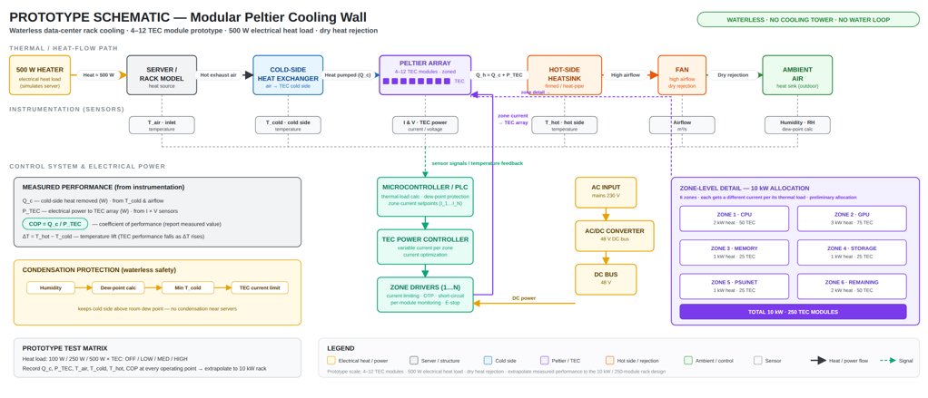
Heat moves server → cold-side heat exchanger → Peltier wall → finned hot-side heat sink → fan → ambient air. The wall never declares maximum current.
Server hot exhaust enters a cold-side air heat exchanger. No contact with electronics — rack exhaust stays inside the rack envelope.
The cold faces of the TEC wall bind to that heat sink. Server-side heat is bound to TEC cold side; airflow loop isolated from ambient.
DC current pumps heat from cold side to hot side. Per-zone current tracks measured load — not one current for the wall.
Finned heat sink absorbs Qc + P_TEC. Sized for both rack heat and TEC power — not just rack heat.
Fans move heat outdoors. No water in. Optional heat-recovery tap for hot water / space heating.
Inlet air · cold side · hot side · humidity · airflow · TEC current + voltage.
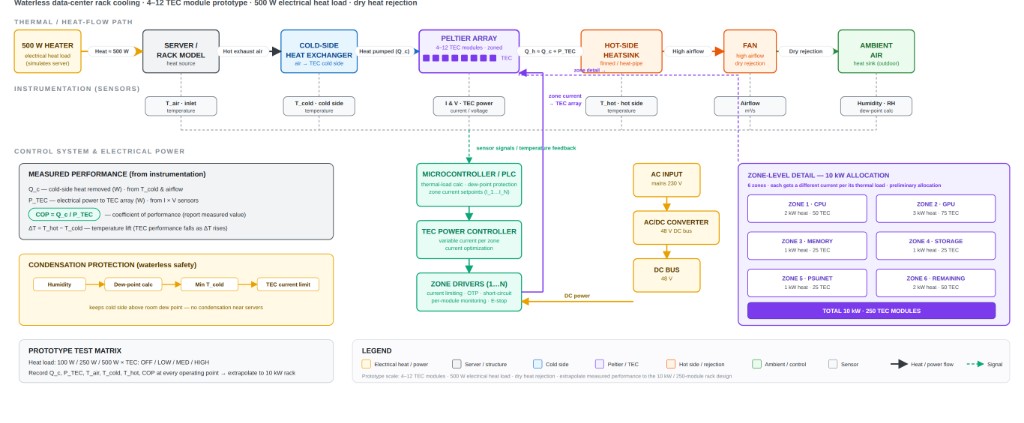
One schematic, one page — server hot exhaust to cold-side air HX, Peltier wall, finned hot-side heat sink + fan, ambient air. Identical to deck slide 5.
Each zone is sized to the heat it carries — current is allocated per zone, not at the wall level.
| Zone | Role | Heat | TEC modules | Character |
|---|---|---|---|---|
| Z1 | CPU compute | 2 kW | 50 | Highest current allocation; tightest target inlet |
| Z2 | GPU compute | 3 kW | 75 | Peak-load zone; bias toward assisted cooling |
| Z3 | Memory | 1 kW | 25 | Lighter load; drifts to free/dry mode |
| Z4 | Storage | 1 kW | 25 | Steady load; light TEC duty |
| Z5 | PSU + network | 1 kW | 25 | Variable; follows workload |
| Z6 | Remaining load | 2 kW | 50 | Buffer zone; absorbs redistribution |
Dry heat rejection handles the load. TEC current ≈ 0.
Only selected zones receive current. The rest stay quiet.
All necessary zones activate. Current capped at the dew-point limit.
"Compute becomes a siting decision again — not a water-permit sequel." Removing water from the cooling constraint list reshapes the data-centre siting map.
Arizona, inland Spain, the Gulf, parts of India, the Chilean coast — sites once penalised for cooling-water draw can now host rack-scale compute.
Northern Europe, Atlantic seaboards, sub-arctic sites — dry heat rejection handles lower-ambient cooling with no evaporation losses.
Repurposed warehouses, light-industrial parks — retrofit-friendly form factor, no cooling-tower permits, no water taps.
Island grids, mining sites, defence outposts, telecom aggregation — previously impractical because water was assumed.
Where water is provable shortage, the wall is now an option on the table alongside immersion, alongside D2C, alongside chillers.
"A medium data centre on evaporative cooling uses around 12,500 gallons a day. A 100 MW+ facility reaches 2 million gallons a day at peak. The Peltier dry wall collapses that line."
| Cooling approach | Direct water use | Per 10 kW rack, per year |
|---|---|---|
| Evaporative cooling tower | High — the workhorse | ~4–8 ML |
| Adiabatic / hybrid dry | Partial saving, still evaporative | ~30–50% less |
| Direct-to-chip liquid | Dielectric fluid · still pumped | Reference case |
| Modular Peltier cooling wall | None — dry rejection | 0 L direct |
Indicative figures: magnitudes vary by climate, density and design. The deck attributes this page's parent numbers to AKCP 2026, MOST Policy Initiative 2025, and the project report. Scaling assumes direct water footprint only — indirect water footprint (electricity generation) is unchanged.
"None of these kill the case for waterless cooling. Each is named in the brief and addressed in the architecture — not hidden in a footnote."
A Peltier module is a heat pump — COP drops as temperature gap widens. The wall must reject both Qc and the TEC electrical power that produced it. Answer: three operating modes keep the wall off-peak when free cooling suffices; zones are sized and current-controlled so the dominant fraction of TEC energy never crosses the ΔT penalty line.
Per-watt cost of TEC modules, drivers and assembly is higher than optimised chilled water today. Answer: the wall is targeted at waterless sites, retrofit interiors, and zones where the water permit is the binding constraint — avoided cost (water, permits, civil works) closes the gap.
Solder fatigue at the hot-side interface, hot-side HX maintenance, and long-term module degradation under thousands of cycles are real over a decade of operation. Answer: ~10% spare modules built in; per-zone drivers carry current limit, OTP, short-circuit and ESD; maintenance paths designed into hot-side HX layout; dew-point limiter caps cold-side temperature where modules are most stressed.
| Item | Detail |
|---|---|
| Category | Modular Peltier cooling wall for data centres (rack-scale) |
| Inventor & patent reference | Mohankumar M · Design + Patent Reference (per Sep 2026 product demonstration deck, slide 1) |
| Prototype | 4–12 TEC modules against a 500 W simulated heat load (slide 5 schematic) |
| Rack-scale target | 250 TEC modules per 10 kW server rack (deck headline banner) |
| Water use | 0 L direct cooling water per 10 kW rack (deck headline banner + slide 7 table) |
| Heat-flow path | Server exhaust → cold-side air HX → Peltier wall → finned hot-side heat sink → fan → ambient air · closed-loop sensors: inlet air, cold side, hot side, humidity, airflow, TEC current + voltage |
| Operating modes | Mode 1: Free / dry cooling (TEC current ≈ 0) · Mode 2: Assisted cooling · Mode 3: Peak cooling (current capped at dew-point limit) |
| Dew-point safety | Dew-point limiter caps cold-side temperature at the most stressed modules |
| Spare / resilience | ~10% spare modules built in · per-zone drivers with current limit, OTP, short-circuit & ESD protection |
| Proprietary company registration | Bestie Technologies Pvt. Ltd. · CIN U85500TN2025PTC186582 · DPIIT DIPP235058 · MSME UDYAM-TN-02-0437576 · GST 33AAOCB1547N1ZD |
"Pick a constrained site. Run the test matrix jointly. Pilot, license, or co-build." Three moves from the deck's closing — talk to the inventor's office.